How to Create a Site Plan: SOLIDWORKS for Architecture Part 2
Design a Building in SOLIDWORKS: How to Show Supporting Infrastructure, Import Topography, set the Perimeter, and create planes, contour lines and surfaces.
Creating The Job Sight
In the first part of this series, we explored using SOLIDWORKS to design buildings such as a shed, barn or house. In this article, we will explore creating the job site, which will consist of capturing the lay of the land and showing supporting infrastructure, such as water, sewage and electrical lines.
It will be necessary to do a bit of homework prior to embarking on this endeavor. Specifically, it would prove useful for you to obtain a satellite image of your property, a topographic map, and a survey map. The topographic and survey map are the most important, and can often be obtained from county websites. Your local code enforcement officer or village clerk may have access to such information as well.
Setting The Perimeter
To create an accurate representation of your job site, the first detail to take care of is establishing the perimeter, or in other words, the border of your property. You can do this in a sketch after starting a new part. Make it a point to set your working units (Tools > Options > Document Properties tab > Units) to a unit system that matches your survey. More than likely, the units will be feet for your length value, and deg/min/sec for your angles.
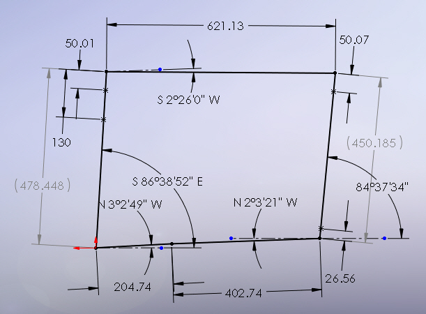
Every property is going to be different, and some will be more difficult to represent in a sketch than others. Typically, it is necessary to place points for reference purposes that describe where a surveyors’ pin is located. Sometimes the pin location can be represented by the endpoint of a line. The example shown in the previous image has multiple pin locations which helped map out adjacent parcels (which are not shown and are not relevant).
If you want to take a more simplistic approach to sketching out the border, you can insert an image of the surveyors map into a sketch (Tools > Sketch Tools > Sketch Picture…). JPG or GIF images work well, to name a few compatible formats. As long as your sketch contains at least one reference line dimensioned to the proper length so that it represents one border line of your property, you can then rotate and scale the image to that reference line. After that, simply sketch the remaining border lines over the top of the image.
Importing The Topography Map
Were you able to obtain a topographic map of your property? If so, this next part can be a lot of fun. Start a new sketch and insert the topographic map using the Sketch Picture command mentioned earlier. Use the options to rotate or scale your topo map (as we’ll call it from here on out) so it matches up to the border sketch you created earlier. The border and topo map may not match with 100% accuracy, for various reasons beyond the scope of this blog, but you should be able to match them up close enough for your purposes.
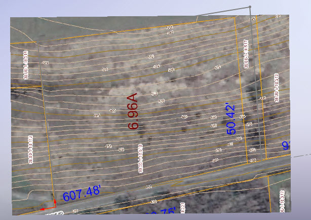
Allow me to give you a better idea of where we are heading with this. The topo map has lines, also known as contours, that conform to differing elevation levels. Drawing all the contour lines on the same plane will not help us, so it will be necessary to create planes at the proper levels. It isn’t hard, but it can be tedious. The topo map in the previous image is of a property on a hill, so it has a fairly large number of elevation levels, and will subsequently need a large number of planes.
Once planes are established, the appropriate contour lines can be created on their respective plane. If this doesn’t make sense yet, stick with me and I will explain in more detail shortly. Once all the contour lines have been created, we will create a lofted surface flowing from one contour line to the next. The surface will be an extremely close representation of the property. Before we are done, you’ll see how easy it is to map out elements of the infrastructure.
Creating Planes
Though it is impossible to see, the topo map in this example has contour lines beginning at an elevation of 432 feet above sea level and continuing uphill until they reach 552. This particular topo map has a contour line for every 4 foot change in elevation. That means we’ll need a plane every 4 feet. Fortunately for us, the SOLIDWORKS Plane command allows for creating a series of parallel planes in one step. I picked the Top plane, set my distance to 4 feet, and create 30 (or so) planes all at once.
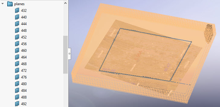
There are different ways to tackle this, but what I recommend is renaming your Top plane to match the elevation of your lowest contour line. In our example, I renamed the Top plane to 436. I created one plane 4 feet below and named it 432. Plane 432 is where I was sketching when I inserted the topo map. That was strictly for sake of convenience. I wanted my topo map to appear closer to where I was working, rather than over 400 feet below where I would be sketching my first contour line. This choice was made strictly for aesthetics and did not affect the outcome.
In my case, planes 432 and 436 aren’t actually used for the property “surface” because their respective contour lines fall on the road and property on the other side of the road. You will definitely want to rename all of your planes to match their respective elevations. It’s the only way to easily stay organized. My first contour line will be created on plane 440.
Creating The Contour Lines
You’ll probably want to start at the bottom and work your way up. Here’s essentially how this works: start a sketch on the desired plane, then draw a spline to match whatever contour line that plane represents. Exit the sketch and repeat for the next contour line.
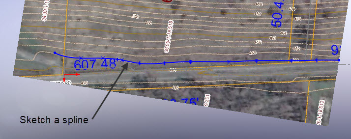
In the previous image, I happen to be sketching on plane 440. Therefore, I sketched a spline over the top of the contour line labeled 440 on my topo map. Fewer spline control points are better. You only want enough control points necessary to match the curve of the original contour line on your topo map. Stick to adding control points at peaks and valleys. The splines should extend a short distance beyond your property border, but they don’t have to extend further than that.
Creating The Surface
Although there were about 30 contour lines in our example, creating the surface is a very straightforward process. This is because there are no areas where the contour lines are closed loops. In other words, no ponds or hilltops. If there were, it would be necessary to complete the surface using a number of steps and various surfacing commands.
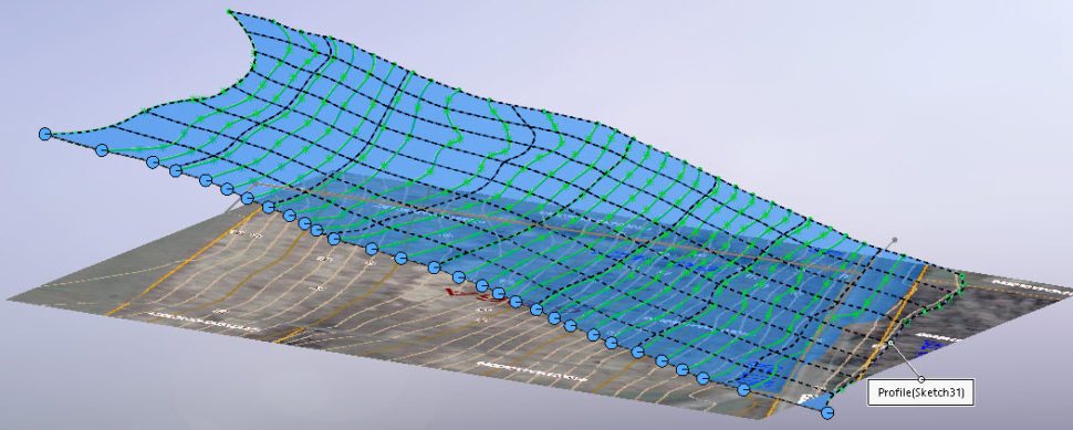
Using the Surface Loft command, we can pick each sketch, being careful to select each sketch in the order we want the loft to blend between them, and near the same endpoint for each sketch contour. The previous image shows the preview prior to clicking the green check to accept the results.
By the way, if you would like to trim the resultant surface down to size, use the original border sketch. Use the Surface Trim command, select the border sketch, and trim away everything outside your property line.
Showing Infrastructure
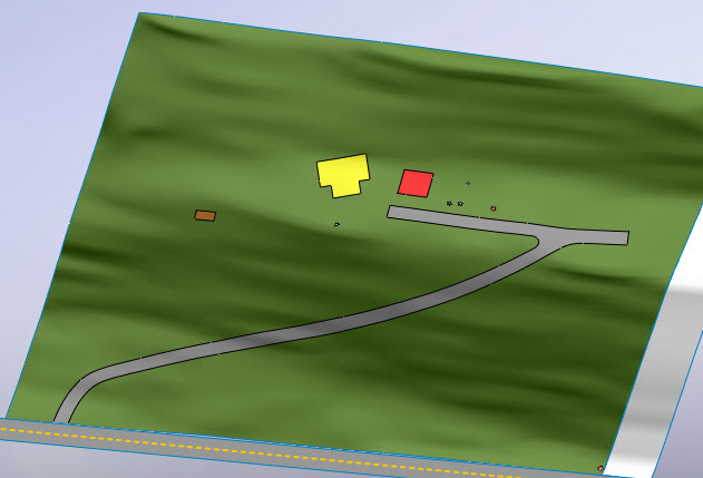
This is the easy part. The command you will be using for this is Split Line, which allows for splitting one face or surface into multiple faces or surfaces. (Incidentally, the term “face” is reserved for surfaces that make up a solid body.) Sketching on the Top plane will work well if we stick with our example, because the Split Line command will project the sketch perpendicular from the sketch plane and onto the property surface. The distance the sketch plane is from the surface it is projecting to is irrelevant.
Want to show where your electrical transformer is located? Sketch an appropriately sized rectangle at the desired location and split the property surface. Change the color of that face to something that stands out. You can model where you want the driveway to go, map out the footprint of your proposed home location, trees you want to keep, or anything else. Use the Spline On Surface command to sketch directly on the surface, if you prefer. This could be useful for showing electrical line runs, water lines, and so on.
Keep it fun, and Happy Modeling!
Up Next
Interior Design: SOLIDWORKS For Architecture Part 3
Up next in our SOLIDWORKS for Architecture series, we’ll be stepping outside of our mechanical design comfort zone and delving into the world of interior design. Have you ever wished you could flawlessly visualize your home’s interior design elements using SOLIDWORKS? In our next installment, ‘Interior Design: SOLIDWORKS For Architecture Part 3’, I’ll guide you through the use of configurations to help eliminate the guesswork and make the best design decisions. We’ll be exploring how to use this incredible software to design everything from windows and doors to kitchen cabinets, and how you can even preview these installations right within your own home using background images. Stay tuned for this exciting journey as we unlock the power of SOLIDWORKS in transforming your home’s interiors from dream to reality.

