The Benefits of Structured-Light 3D Scanning for Manufacturing, Reverse Engineering and Quality Control Workflows
The Benefits of Structured-Light 3D Scanning for Manufacturing, Reverse Engineering, and Quality Control Workflows
The origins of 3D Scanning and the history of metrology is a fascinating one. Though some might agree with the maxim “man is the measure of all things,” as a species we’ve always been tool builders. This is an unchangeable and mostly traceable fact, though the methodology developed over the course of history has changed directions many times.
Units of measurement evolved in different ways depending on the culture and location of human civilization during various periods of time. The grain was perhaps the earliest unit of measurement, taken from a single grain of wheat or barleycorn. These units would be used to measure precious metals like gold and silver. There are traces of ancient units of measurement in today’s units of measurement. The pound, used by the United Kingdom, evolved from the Near Eastern mina, which was a unit of weight that could be divided into 60 shekels. Another relatively unchanged unit of measurement is the carat, which is used for measuring the weight of gemstones.
However, the standardization of units and modernization of metrology occurred during the French Revolution. The desire for standardization was political and led to the creation and adoption of the decimal-based metric system.
Perhaps one of the all-time greatest inventions is a tool known as a caliper, which was created and used by civilizations dating as far back as the 6th century BC. Calipers evolved from relatively simple ones until 1851, when American inventor Joseph R. Brown designed and constructed his Vernier caliper, which was accurate to within thousandths of an inch. Over time, this turned into a digital caliper like the one shown in Figure 1.

Product Design Workflow: Calipers Versus 3D Scanners
Using calipers, engineers could take precise measurements of an object and replicate it in two dimensions, vis-à-vis drawings. As everything physical in modernity became digitized, so did the caliper. But soon, the digital caliper had a new ally in computing: computer-aided design (CAD). CAD began its rise in popularity among designers, artists, and engineers starting in the early 1980s. Using precise measurements taken from digital calipers, product designers could enter Cartesian coordinates of measurements into programs such as AutoCAD, recreating the shape of a physical object in a digital representation for the first time.
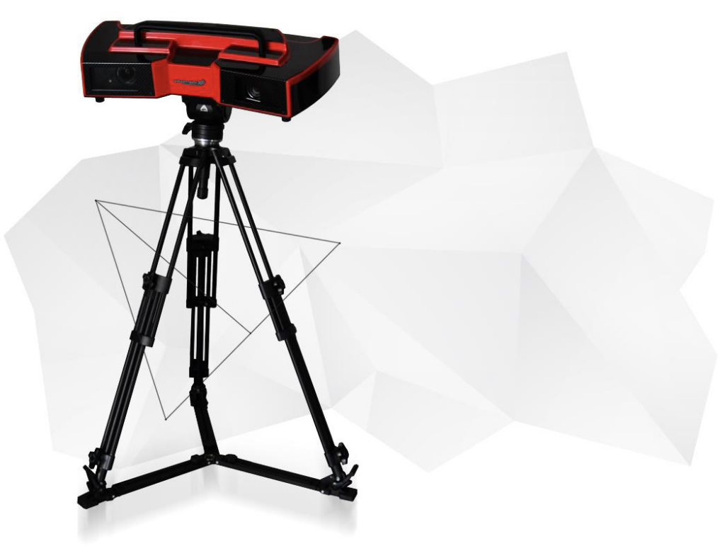
3D scanning technology was developed largely during the 1960s in order to capture the precise surface geometry of objects. Once an object’s geometry was captured, engineers and researchers hoped that they could find efficient ways to recreate the shape of these surfaces with increased speed and accuracy. Early 3D scanners used components such as cameras, lights, and projectors to achieve the first 3D-scanned models. The problem at the time was that the techniques and equipment used for 3D scanning created a massive amount of data that was too unwieldy for hard disk storage drives. The process was also incredibly time-consuming. Then in the 1980s, the development of laser optic technology and its subsequent integration into 3D scanning technology laid the foundation for modern 3D scanners (see Figure 2).
Types of 3D Scanners
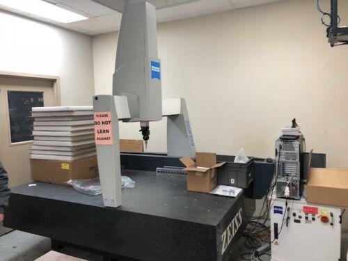
Coordinate-measuring machines (CMMs) use a combination of transducer technology and a contact measuring probe to measure points and geometry including but not limited to cylinders, cones, spheres, planes, lines, and circles. There are two types of CMM: direct computer control (DCC) and free-floating (manual). The difference in part inspection between the two types of machines is significant because free-floating CMMs rely on a human operator, whereas DCC CMMs are automated.
Noncontact Active Laser 3D Scanners
Active laser 3D scanning technology works by utilizing two technical methodologies: time-of-flight and triangulation. A time-of-flight laser scanner maps out each Cartesian coordinate (x, y, z) by measuring the return trip of a laser to a given point and back. Triangulation works by similarly sending out a laser point, except with this method a camera is used to find the point in its field of view. The laser point, camera and laser emitter form a triangle and take the measurement of the point relative to the total scanned area.
Noncontact Structured-Light Scanning Versus CMMs
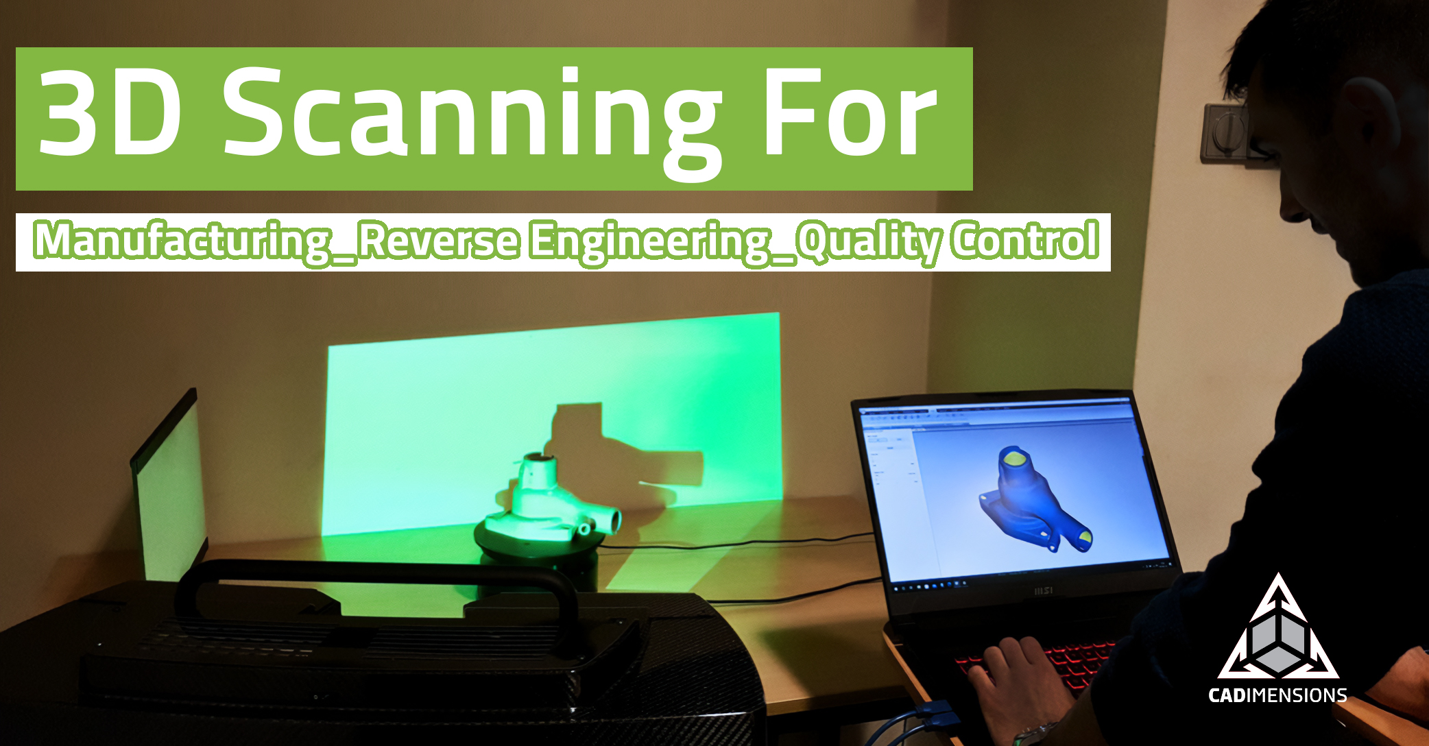
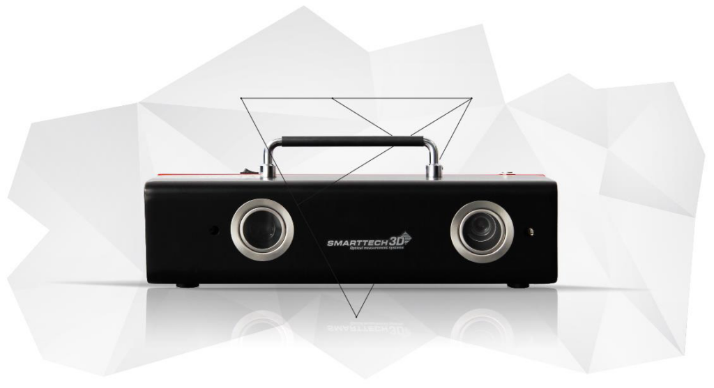
SMARTTECH3D uses a different type of noncontact active 3D scanning called structured-light 3D scanning. This technology uses one or more cameras that position themselves by way of part geometry or by offline targeting. With a single camera, the position of the light projector relative to the camera must be determined ahead of its use. When structured-light 3D scanners have two cameras, calibration must occur simultaneously between the pair. Some structured-light scanners use green-light scanning, but SMARTTECH3D is worth singling out with respect to metrology and the superiority of how its products measure an object’s surface geometry using blue-light structured-light scanning over digital calipers and CMMs.
In fact, SMARTECH3D received a certificate of accuracy from the Laboratory of Coordinate Metrology after undergoing arduous and intensely critical rounds of independent testing. Besides product design, the structured blue-light scanning works very well for manufacturing and inspection. In manufacturing, quality control requires absolute precision.
How does SMARTECH3D Structured-Light Scanning Compare to Today’s CMMs?
Coordinate-Measuring Machines Are Materially Invasive and Expensive
The first thing to remember is that the quality of today’s coordinate-measuring machines (CMMs) are largely dependent on the quality of software that runs their mechanical systems. These systems utilize transducer technology and a contact measuring probe, which can take immediate Cartesian coordinate snapshots or utilize articulating continuous contact probing within a specific measurement envelope. There are CMMs available for large-scale products in the automotive and aerospace industries due to constraints vis-à-vis volumetric accuracy. So, as a rule of thumb, the larger the CMM system, the less accurate it becomes. Extremely precise CMMs for large-scale CAD model-based inspection do exist, but they are extremely expensive.
Structured-Light Scanning Is Better for Manufacturing and Inspection
The higher degree of accuracy found in SMARTECH3D Green-Light 3D scanners makes it easier to inspect parts and amplifies the effectiveness of quality control methodology. One of the most common types of noncontact 3D scanning is structured-light scanning.
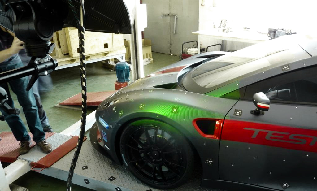
Like CMMs, structured-light scanners come with measurement envelopes that range from the very small (for inspecting micro-machined components) to the very large (for use in automotive manufacturing, reverse engineering, quality control and parts inspection). But structured-light scanners differ greatly from CMMs in that they do not actually touch the material being scanned, which is especially important in cases such as scanning and digitally archiving historic artifacts). When it comes to capturing complicated geometry, structured-light scanning is far superior to CMMs.
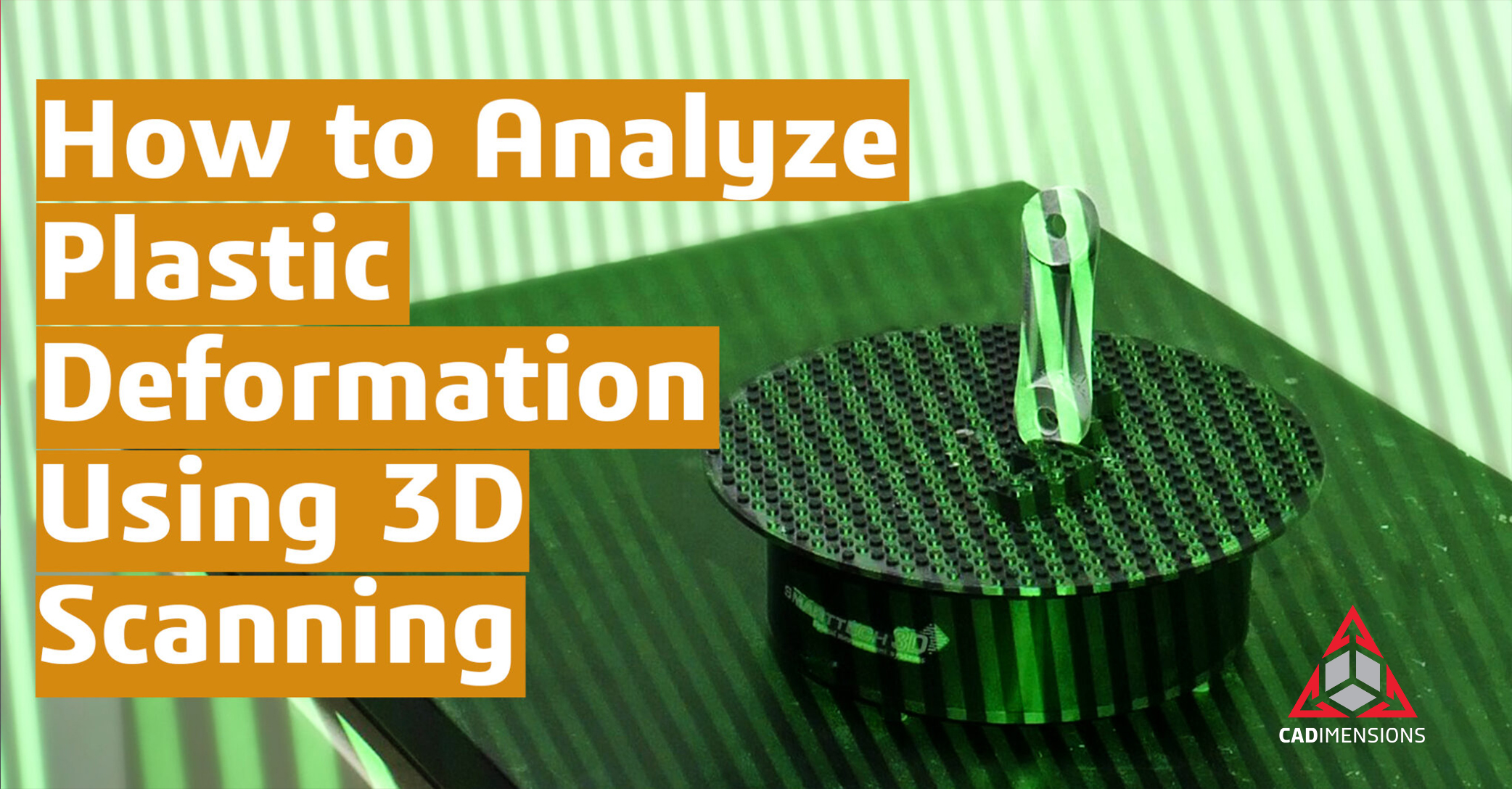
Unsurprisingly, a projected array of parallel lines made from green light capture intricate distortions from different angles much better than a contact measuring probe from a CMM. The camera or cameras capture these intricate distortions by way of triangulation and conversion into cartesian (x, y, z) coordinates much more quickly and densely than CMMs. If the material that makes up the part, object or component is not rigid, CMMs will not be even close to as accurate as structured-light scanners. For example, a CMM used on soft rubber or silicone parts would produce inaccurate geometric readouts of the material.
With processing the structured-light scanning data, which is far denser than data from a CMM, a much more accurate 3D mesh is created from powerful software such as Geomagic, which combines multiple scans. This mesh 3D model can then be used to perform dimensional inspection and reverse engineering operations. But software like Geomagic Control X can be used for both part verification and validation.
Inspection, Verification and Validation with Geomagic Control
Geomagic Control is a metrology software used to perform many different functions in quality management workflows. using the data from the structured light 3D scanner, Geomagic Control allows users to understand both the process and product design life cycle. Users can assess out-of-tolerance conditions using analysis features.
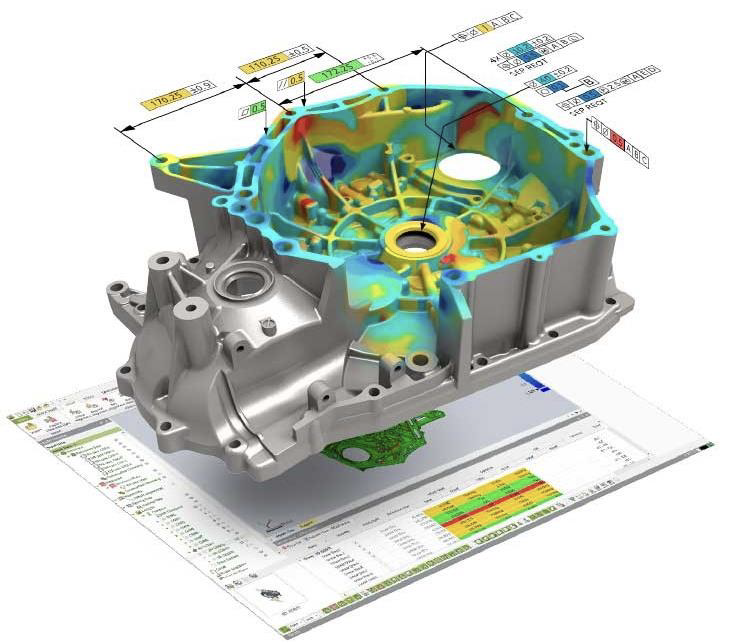
Inspection results are available to share via a PDF report complete with embedded 3D models, numeric inspection data, multiple views and full 3D deviation color mapping.
Using 3D Scanning Services Saves Time
With product design, reverse engineering and quality management, time is of the essence. The faster you can get a product to market, the more you can reduce the cost, and the higher your competitive advantage and profit margin will be. Scanning services such as those offered by CADimensions are available immediately to help manufacturers with their 3D scanning needs . Sometimes work needs to be outsourced in times of extreme business. Structured-light scanning technology like that used in the SMARTECH line of products can help businesses perform reverse engineering and quality control workflows quickly and efficiently.
Bottom Line
Bringing structured light 3D scanners like those from CADimensions and SMARTTECH3D in-house will help save time and reduce costs in product design and manufacturing workflow, and enable better quality control. Any company, group or individual can purchase a 3D scanner and Geomagic Control software, or use 3D scanning services to their benefit. As for digital calipers and CMMs, they are useful tools to be respected, but they are going the way of the dodo.

